The Essential Ballfield Guide Produced by Beacon Athletics since 2007
Welcome to the definitive resource for ballfield design, construction and renovation. This expanded fourth edition brings you several noteworthy updates. Most importantly, the experts at Beacon Athletics and DuraEdge have combined forces to deliver the most complete Ballfield Guide ever.
We know you’ll face a critical aspect in the performance of your infield right from the start. So for the first time, we go in depth with what you need to know to make sure your infield soil is properly installed.
In anticipation of a trickle down effect over the next few years, we’ve also updated our how-to for the installation of base anchors with the MLB and MiLB moving to 18″ bases. And in this edition, we walk you through the pros and cons of artificial and natural pitching mounds.
We know this guide will become one of the most valuable tools in your shed. But please don’t hesitate to contact the industry leaders at DuraEdge and Beacon Athletics if you have any questions or reference the online resources at Ballfields.com/guide for an interactive experience with the information in this guide.
Be sure to consider the handy 56-page printed version (BUY NOW) of the Guide.
 You can also try the online flip-book version of the Ballfield Guide…
THE ONLINE BALLFIELD DESIGN & DIMENSIONS GUIDE
► Ballfield Layout
- Managing Your Project
- Space Needs of a Ballfield
- Laying Out Your Ballfield
- Which Layout Makes Sense?
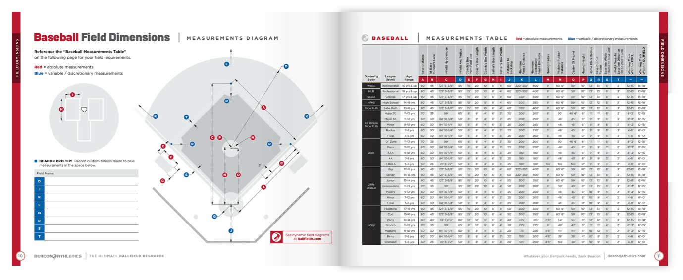
► Ballfield Dimensions
► Field Amenities
► Infield Soils
- Infield Soil Overview
- New Versus Existing Infields
- Function of Soil Entities
- Engineered Soil or Native Soil?
- How and Why to Test Your Soil
- Understanding Test Results
- Determining Your Infield Soil Needs
- About Topdressing: Why You Need It
- Topdressing Amounts
- Installing Your Infield Skin
► On-Field How-Tos
► Mounds & Batter’s Boxes
- Artificial vs. Natural Mounds
- Building a Pitching Mound
- Pitching Mounds & Circle
- Batter’s Box & Catcher’s Box
► Warning Tracks